by Matt
5. March 2012 03:03
1. Remove the three screws loated at the of the machine and remove top cover.
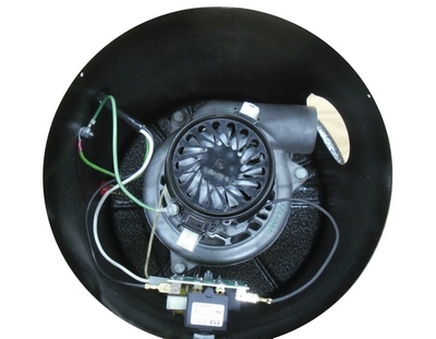
2. Disconnect all of the wire from the circuit board with needle nose plires.
3. Remove the nut from the front of the circuit breaker, and also remove the front screw just below the nut.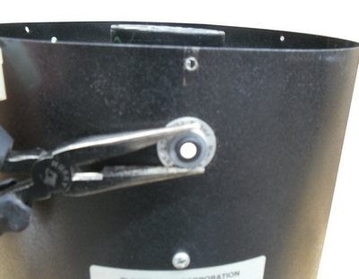
4. Once the circuit board has been removed, you will need to drill a 3/4" hole where the screw in the circuit board has been removed.
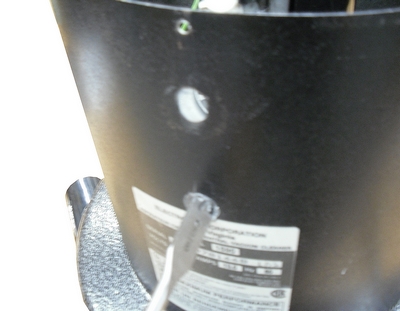
5. After the hole has been drilled, you can now insert the circuit board into both holes and lock into place with the nuts provided. The low voltage wires will now be connected into the new circuit board and the old red low voltage receptical will no longer be used.
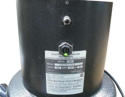
6. Next proceed to connect all the wires to the circuit board: 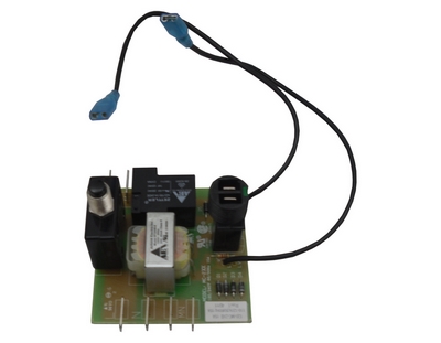
-Connect the black cord lead to L (The top contact on the left side, looking at the front of the circuit board).
-Connect the white cord lead to N (The second contact on the left side, looking at the front of the circuit board).
-The third contact is left blank.
-Connect any of the two motor leads to MN (The fourth contact on the left side, looking at the front of the circuit board).
-Connect the last motor lead to the top contact on the right side, when looking at the front of the circuit board.
-The second terminal on the right side, when looking at the front of the circuit board is left blank.
-The two wires on the bottom of the circuit board are not used on Electrolux model 1590, they are used for a filter lock out swith on a newer model. You can tape them back, or cut them off so they are out of the way.
7. You are now ready to put the top cover back on and test the unit.
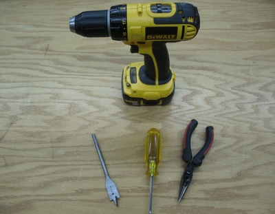
Tools Required:
-Electric Drill
-3/4" Drill Bit
-Phillips Head Screwdriver
-Needlenose Pliers
If you require any questions with this installation please call 866-972-8227 and one of our technicians will be happy to assist you.